
I2C Address Guide: Master the I2C Protocol and Bus
Every embedded electronics project eventually requires a reliable data communication method. If you want to connect multiple sensors to a single microcontroller without running out of pins, understanding the I2C address system is essential. Inter-Integrated Circuit (I2C) is a synchronous, multi-device, half-duplex serial communication bus that lets dozens of integrated circuits co-exist using just two wires.
In this I2C address guide, you will learn how the protocol works, how to calculate device addresses, and how to interface popular chips. If you are new to hardware protocols, you might also want to read our [Internal Link: introduction to microcontrollers] to understand how these chips process data.
The I2C Address Architecture: 7-Bit vs. 8-Bit
Every slave device on an I2C bus must have a unique identity. This unique identifier is known as the I2C address. If two devices share the exact same address on the same wires, they will conflict, corrupt data, and crash the entire bus line.
How to Calculate the I2C Address
Technically, standard I2C uses a 7-bit address structure. This allows for up to 128 unique devices on a single bus (2⁷ = 128). However, when data is actually transmitted over the wire, it is sent as an 8-bit byte.
+-----------------------------------------+

| Bit 7 | Bit 6 | Bit 5 | ... | Bit 1 | Bit 0 |
+-----------------------------------------+

|        7-Bit Device Address         | R/W   |
+-----------------------------------------+
The 8-bit byte is constructed like this:
- Bits 7 to 1: The actual 7-bit device I2C address.
- Bit 0 (LSB): The Read/Write (R/W) bit. A
0indicates a Write operation, while a1indicates a Read operation.
Because of this layout, datasheets can be incredibly confusing. One datasheet might list a sensor’s address as 0x50 (the 7-bit version). Another might list it as 0xA0 for writing and 0xA1 for reading (the 8-bit versions). Arduino Wire libraries and Raspberry Pi tools automatically expect the 7-bit version (0x50) and handle the math for you.
Popular Devices and Their Standard I2C Address
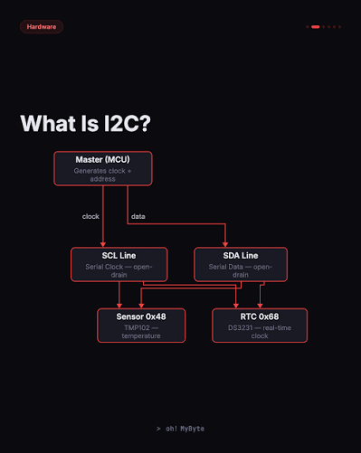
If you are building embedded projects, you will inevitably encounter these classic integrated circuits. Below is a diagram showing a typical multi-device bus setup, followed by a reference table of common default hardware addresses.
       [ Microcontroller / Master ]

             |              |
             | SDA          | SCL
       +-----+--------------+-----+

       |                          |
+------+------+            +------+------+

|  OLED Screen|            | RTC Clock   |
| Address 0x3C|            | Address 0x68|
+-------------+            +-------------+
| Device Category | Part Number | Default 7-Bit I2C Address | Description |
|---|---|---|---|
| Real-Time Clocks | DS3231 / DS1307 | 0x68 | Keeps highly accurate time/date tracking with battery backup. |
| OLED Displays | SSD1306 (0.96″) | 0x3C or 0x3D | Highly popular monochrome displays for user interfaces. |
| Inertial Measurement | MPU6050 | 0x68 or 0x69 | 6-axis accelerometer and gyroscope for motion tracking. |
| Barometric Pressure | BMP280 / BME280 | 0x76 or 0x77 | Measures atmospheric pressure, temperature, and humidity. |
Pro-Tip: Many of these chips feature physical pins on the board labeled A0, A1, or A2. By tying these pins to Ground (GND) or Power (VCC), you can alter the lower bits of the hardware address. This allows you to run multiple identical sensors on the same bus without an address conflict. For more tips on layout design, check out our [Internal Link: PCB design best practices].
How to Find an Unknown I2C Address
If your sensor lacks documentation, you can easily use an address scanning sketch to find its location on the bus.
Step 1: Wire the Hardware Properly
Connect your device to your microcontroller using standard mapping:
- Sensor VCC → Microcontroller 3.3V or 5V
- Sensor GND → Microcontroller GND
- Sensor SDA → Microcontroller SDA (Pin A4 on Arduino Uno)
- Sensor SCL → Microcontroller SCL (Pin A5 on Arduino Uno)
Step 2: Run the I2C Scanner Code
Upload this code to find the exact I2C address of your connected device.
#include <Wire.h>

void setup() {
  Wire.begin();
  Serial.begin(9600);
  while (!Serial);
  Serial.println("\nI2C Scanner");
}

void loop() {
  byte error, address;
  int nDevices = 0;

  Serial.println("Scanning...");

  for(address = 1; address < 127; address++ ) {
    Wire.beginTransmission(address);
    error = Wire.endTransmission();

    if (error == 0) {
      Serial.print("I2C device found at address 0x");
      if (address < 16) Serial.print("0");
      Serial.print(address, HEX);
      Serial.println(" !");
      nDevices++;
    }
  }
  if (nDevices == 0) Serial.println("No I2C devices found\n");
  else Serial.println("done\n");

  delay(5000);
}
Troubleshooting Your Dynamic I2C Address Issues
If your scanner script returns “No devices found”, check these common hardware pitfalls:
- Missing Pull-Up Resistors: I2C relies on an open-drain architecture. You must have 4.7 kΩ to 10 kΩ resistors pulling both SDA and SCL up to VCC.
- Voltage Incompatibility: Never connect a 5V microcontroller directly to a 3.3V sensor without a logic level shifter, or the bus will fail to pull signals up correctly.
- Wire Length: I2C was designed for short PCB traces. If your wires exceed 30 cm, high capacitance can warp the clock edges, masking the true I2C address from the master.